
AI Data Center Cooling for Mixed-Density IT Halls at Scale Mixed-Density IT Halls at Scale
Mixed-density AI halls combine liquid-cooled accelerators with air-cooled networking and storage. Here is how design teams should scope cooling architecture, controls and operating limits before commissioning.
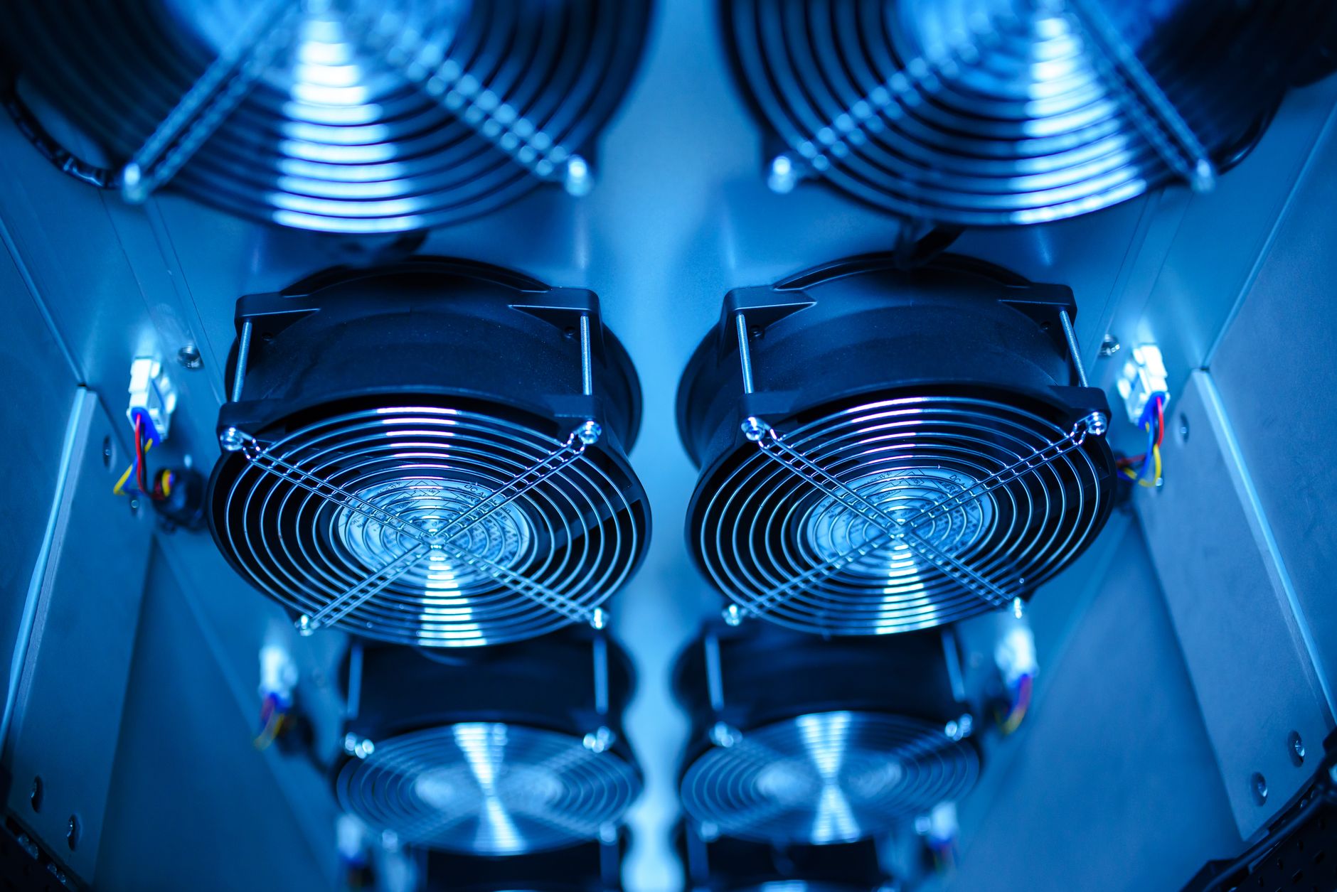
An AI data hall is rarely a single-cooling-mode environment. Accelerator clusters sit on direct-to-chip liquid loops, while networking switches, storage arrays and power conversion equipment remain on precision air cooling. That mix — not the liquid loop alone — is what defines the cooling envelope of a modern intelligent computing facility, and it is where most commissioning disputes originate.
AI accelerator clusters create concentrated heat and rapid workload swings. A training job that sits idle for an hour can ramp to full power in seconds, demand sustained cooling for days, then drop to standby just as abruptly. Cooling has moved from a facility-engineering afterthought to one of the two or three subsystems that constrain how much usable compute a hall can deliver. In this context, AI data center cooling is best understood as a combination of specific components, controls and operating interfaces — not a single isolated device.
Scope the Cooling Load Before Choosing Equipment
The first question on any mixed-density IT hall is not "which product" but "which heat loads, by rack, by circuit, under which operating pattern." Networking switches, storage and power conversion typically still need precision air cooling even when accelerators are on liquid loops. Equipment ratings, control policies and the responsibilities of the operating team should be aligned before commissioning begins, not negotiated during it.
Designers should distinguish IT-side thermal design power (TDP) from the operating heat load produced by actual training jobs. Both numbers matter. Peak capacity sets the envelope. Part-load behaviour determines how efficiently pumps, fans and chillers run across the duty cycle the hall will actually see.
A design assumption that cannot yet be confirmed by measurement should be documented as an assumption, with the measurement method noted. Cooling plans that quietly treat assumptions as facts produce the commissioning surprises that lead to inlet-temperature excursions in the first months of operation.
Cooling Paths From Chip to Plant
The air side remains important. Fans, in-row units and aisle containment collect residual heat from memory modules, networking equipment and other devices that are not fully liquid cooled. A plan that focuses only on the liquid loop can leave inlet temperatures outside server specification even when the chip cold-plates are performing exactly as designed.
In a mixed-density hall, three heat-removal paths typically coexist:
- A direct-to-chip liquid loop serving accelerators and, increasingly, memory
- A precision air path for networking, storage and ancillary equipment
- A plant-level heat rejection path — chiller, dry cooler, cooling tower or combination — that ultimately rejects both
Each path has its own instrumentation, its own control logic and its own failure modes. Treating them as one system without mapping the interactions is the most common architectural error in halls built in the last three years.
Liquid Flow, Supply Temperature and Air Control
Coolant flow rate and supply temperature should follow the server manufacturer's documented operating limits. The tolerances are tighter than they look. A supply temperature a few degrees above spec can cut chip clock speeds; a few degrees below can introduce condensation risk on surfaces in the cold aisle.
Pump redundancy, automatic isolation and calibrated differential-pressure measurements help preserve stability when devices are added or removed from a circuit. The thermal management system should correlate rack temperatures, coolant supply and return conditions, and plant equipment states — ideally in one view, with alarms defined against each parameter. Trends from one loop cannot be assumed to represent another loop with different loads or hydraulic resistance.
On the air side, the equivalent discipline is aisle-containment integrity, differential pressure across the containment boundary and consistent server inlet measurement. In mixed halls, air flow patterns shift when liquid-cooled rows are added; the air plan should be re-validated, not inherited.
Reliability Under Computing Loads
Liquid leak sensors and isolation valves need a defined alarm sequence that protects IT equipment without unnecessarily shutting down unaffected loops. The design should document which events require manual intervention and how the IT team is notified — in writing, before go-live.
Redundant pumps or cooling units require more than spare nameplate capacity. The hydraulic routing, power supplies and control logic must still operate after a credible component failure, and the failover should be proven in commissioning, not assumed from a nameplate rating. Operators who have inherited systems with "N+1" pumps sharing a single control board and a single power feed know how quickly that redundancy can evaporate.
A useful commissioning discipline: write down the top ten failure modes the design is supposed to tolerate, and walk through each one on the live system. Simulated leak, pump trip, chiller loss, loss of chilled-water supply, isolation valve failure. If the recovery sequence requires more than the documented operator response, the design has an undocumented dependency.
Efficiency, Scaling and the Right Set of Measurements
Expansion requires coordinated headroom in the water plant, electrical distribution, headers and data hall floorplan. A coolant distribution unit (CDU) added without sufficient upstream heat-rejection capacity does not increase sustainable rack power. It simply moves the bottleneck further down the chain and makes it harder to diagnose when the hall starts throttling.
Operators tracking facility performance should go beyond power usage effectiveness (PUE) as a single headline metric. A mixed-density AI hall benefits from a layered measurement set:
- Cooling electricity as a share of total facility draw
- Server inlet compliance — the percentage of racks whose intake air stays within the ASHRAE recommended envelope
- Coolant approach temperature at the CDU — how close the supply temperature sits to the chilled-water supply
- Thermal incident rate — the frequency of inlet or coolant excursions per month
These together give a picture that PUE alone cannot. PUE flatters halls that run their chilled-water loops hot; it penalises halls that have invested in redundancy. The composite view surfaces both.
Architecture, Interfaces and Operating Limits
The decisive question for any mixed-density AI hall is whether the specified cooling architecture, operating limits and interfaces are supported by the actual site, the actual equipment and the actual operating model. A clearly defined liquid loop paired with a suitable air path and instrumentation that identifies where heat is moving supports the reliability of AI workloads without assuming uniform rack density.
Specification of a AI data center cooling system should therefore list — explicitly — the air-side and liquid-side operating ranges, the redundancy assumptions that have been tested in commissioning, the alarm sequence for each credible fault, and the measurement points the operating team will use day-to-day. Selection against applicable standards, site conditions and model-specific documentation then becomes a straightforward engineering exercise rather than a late-stage negotiation.
What the Operating Team Needs at Handover
Before the hall is accepted, the operating team should have the current cooling diagram, the normal set of indicators and alarm thresholds, the first-response procedure for each credible fault, and the contact chain for escalation. Measurement baselines — typical approach temperatures, typical pump speeds, typical server inlet distribution — should be captured in the first weeks of operation and documented as the reference for future drift analysis.
An accurate handover is not an administrative task. It is the artefact that lets the operating team diagnose a slow efficiency loss six months in, catch a drifting valve before it becomes a thermal incident, and demonstrate — if asked — that the cooling architecture is operating within its designed envelope.
Continue reading


The Entrepreneur Story
Is your story worth telling?
We feature founders who are building something real. Apply and we'll be in touch.
Apply to be featured →Stay sharp.
Ideas that move.
Founder stories, emerging ventures, and essays on what's next — straight to your inbox.
Unsubscribe any time.